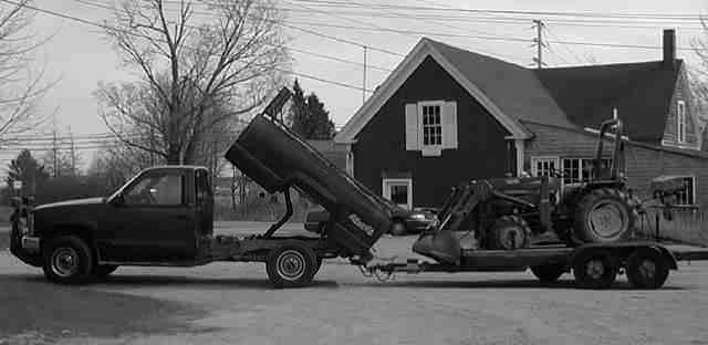
While I didn't miss feeding that beast (10MPG empty) or throwing parts at it, I have missed having that dump capability. I'm too damned old to be running a Mexican Backhoe when it's time to unload a yard or two of compost or whatever.
If you've been wandering around my site, you may have noticed that I'm something of a pack rat. I retired as of October 1st, 2012, so I have plenty of opportunity to indulge my favorite passtime, building stuff as cheaply as possible out of whatever I have laying around. A quick inventory of my collection showed that I had most of the stuff I needed to build myself a dump trailer. Best of both worlds: No shoveling, no expensive truck to maintain or put gas in.
So, out of various buildings and cultch piles, I collected the following:
1. A self-contained hydraulic pump, reservoir and valve assembly (Got it off Craigslist years ago, came off a small dumptruck)
2. A 48" hydraulic cylinder (Came off a jib crane we scrapped when I worked at the cannery)
3. A 5.5 HP Honda engine with a gear reduced output of 650RPM at full throttle (Declared surplus when I worked at the rental outfit)
4. An axle, with hubs, rims and tires (Don't recall where that appeared from)
5. A heavy duty trailer tongue, 3x3 Schedule 80 square tubing with a trailer hitch bolted onto it (Old boat trailer somebody gave me)
6. The remnants of an old Kemp Chipper/Shredder to mount the Power Pack (Engine and Pump) on. Given to me intact by someone who was done with it. Sold the engine, used a bunch of other stuff off it for other projects. The frame and wheels remained in my scrap pile.
7. Steel from a multitude of sources including galvanized H-beam from highway barriers, frame rails from an old tractor, and taking a torch to an old project I lost interest in.

| 
| 
|
The first step was to build a subframe with an axle. The frame rails are the aforementioned highway H beams, the cross pieces are tractor frame rails.
The axle was cut, shortened to fit and rewelded. I didn't have a set of leaf springs (recycled for a few bucks, silly me...) so I scrounged a set from a neighbor that was scrapping a small trailer. The springs might be a little light for a full load, but it's not a huge issue if the axle bottoms out. I may put some rubber bumpers in if I can find a set. This step also included my first cash outlay: A spring mounting kit with U bolts and axle plates.

| 
|
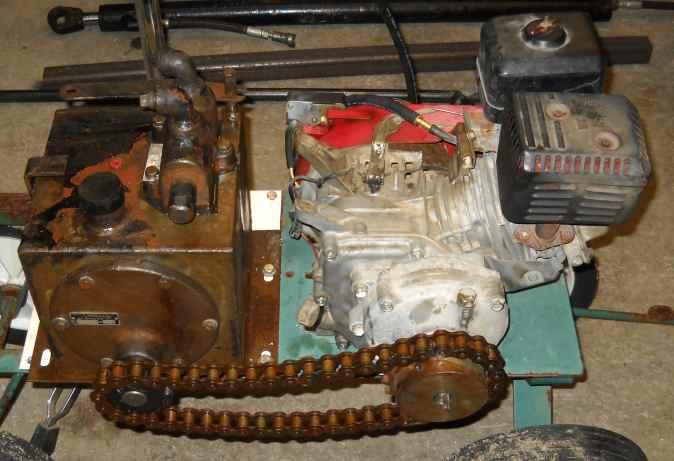
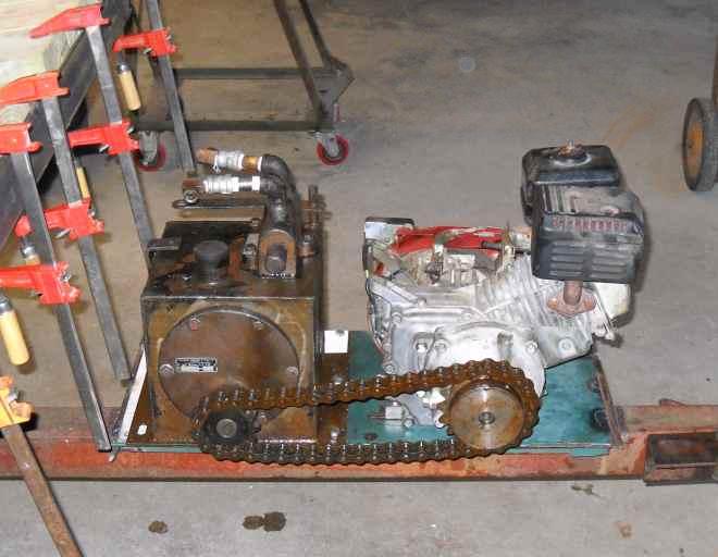
The next step was to ensure my hydraulic components were usable, and devise a way to mount the pump and engine. After disassembling and flushing the pump and making a couple of new gaskets all was good to go.
The engine already had a 60 pitch sprocket on it, and I had a bunch of 60 pitch chain laying around, so I made my second cash outlay: A sprocket for the pump drive.
The assembly is mounted on the shredder chassis. It worked out well as the engine mounting plate was already slotted to a standard mounting footprint, so I just bolted the engine to it and drilled a couple of holes to mount the pump. Later in the process, the wheels and such will be cut off and the assembly mounted to the tongue of the trailer.

| 
|
With the subframe essentially done (minus the tongue, more on that in a bit) it was time to start on the dump frame. I didn't have any suitable steel for that, so I was forced to make my third cash outlay, a 20' piece of 3" channel for the perimeter frame. For a 4x8 bed, I needed 24 feet, but I happened to have one piece that would make up the difference.
Just a matter of clamping the long members to the subframe, pulling the diagonals to make sure they were parallel and square, and welding the end pieces in.

| 
|

| 
|
With the frame in place, the next step was to manufacture and install the hinges and the hydraulic cylinder mounts. I based the general layout on a commercially-built dump trailer that I stopped and looked at.
The hinges are made of 1/2" thick 3" wide plate, two on the dump frame straddling one on the subframe, and pinned together with a piece of 1" round stock. The fit is loose enough that I didn't bother to make it a greaseable connection.
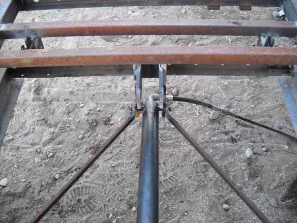
Initially, the cylinder was oriented with the fixed point on the front of the subframe. I extended the mount out to provide clearance for the hose connection, which on this cylinder happens to be tapped directly into the end of the cylinder. The pin for this mount was bored and cross-drilled and a zerk threaded into the end to make it greaseable.
The moving end of the cylinder is permanently lubed and doesn't need a grease fitting. The mount is welded to the Schedule 80 2x2 crossmember.
With the frame hinged and the cylinder installed, I rigged a temporary hookup to check the geometry. I was just going by instinct and my memory of the trailer I looked at. As you can see, it worked, but it was pretty jerky. I was also concerned that due to the length of the cylinder, the lift point was very close to the hinge point (about a foot or 16 inches) and it was going to take a LOT of leverage to start the load.
So, after mulling it over and consulting with some friends, I decided to swap ends, fixing the cylinder to the rear of the subframe and moving the lift point to the front, as far away from the hinges as possible.
| 
|
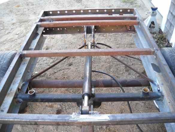
The simplest way to accomplish this was to rotate the dump frame 180�, cut off the hinges and re-weld them onto a new crossmember which was then welded in the appropriate place.
Flopping the cylinder around wasn't quite as easy. Initially, I just duplicated the mount I used on the front of the frame and welded it on the rear of the frame. A quick test with the temporary hookup revealed that the cylinder was too nearly horizontal and just wanted to spread the frame.
So, I had to drop the rear of the cylinder 6 inches to give it a better lift angle. This worked, but the extra leverage was twisting the heck out of the subframe crossmember, so some bracing to triangulate the mount was required. Burned up an entire day and a significant portion of my vocabulary, but it works MUCH better..
| 
| 
|
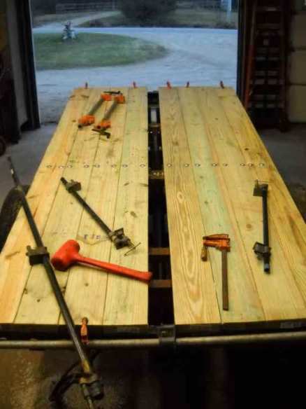
With the hydraulic geometry figured out, I moved on to decking the trailer and mounting the power pack.
After pricing various options, I decided to deck the trailer with pressure treated 2x6. The planks are captured under a piece of 3x3 angle in the front which is welded to the deck frame. They are carriage-bolted to a crossmember in the middle, and captured under another piece of angle in the rear which is bolted in place. This way, if the deck needs to be replaced, I can unbolt the rear and center and slip them out from under the angle in the front. Fourth cash outlay: 2x6's and galvanized carriage bolts.
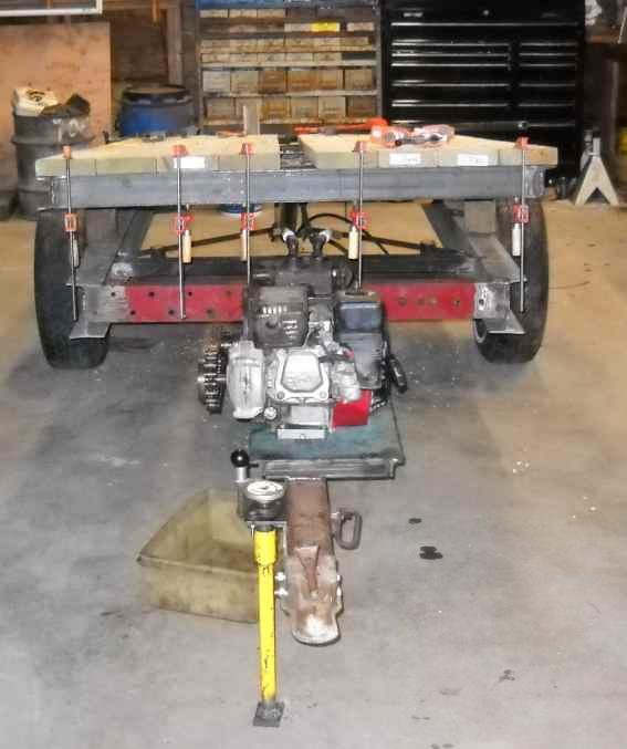
The power pack assembly was cut off the shredder chassis and welded to the tongue of the trailer. A chain guard and a little additional bracing for the mounting plate will be added.
Now that the physical layout was pretty well determined, I made my fifth cash outlay for hoses and fittings for the hydraulics. When UPS dropped them off, I plumbed things up and discovered another problem: The pump was designed for a MUCH bigger cylinder and flowed so much oil that the cylinder SHOT up and jerked things around so much that it broke a couple of temporary welds.
After indulging in a little Anglo-Saxon verbal relief, I did some research and decided the best way to calm things down was to install a flow divider to divert some of the excess flow to the return side. Commercial units are pretty spendy, so I went with my specialty: jury-rigging things out of what I have laying around.
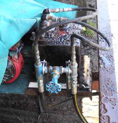
Presenting the Redneck Flow Divider (RFD)! A tee in each line, connected by a gate valve across the tees. Crack open the gate valve to bleed off unneeded pressure/flow. Adjustable on the fly...close it completely to provide full pressure to start a heavy load, crack it open to control lift and/or drop rate as needed.
With the hydraulic system figured out and the plumbing neatened up, it's time to see if this thing will lift an actual load. As you can see, with the current 18:12 gearing, it's everything that motor wants to lift a full load. I'll change the gearing to 12:35 when the proceeds of my sixth cash outlay, a larger sprocket and a new tank for the engine, come in.
The new gear came in and I now have it geared at 18:35 (forgot the engine has a different shaft size, so kept the original gear). The gas tank is installed and I loaded a BIG old load of sheep manure and wet hay on it. Darn thing wouldn't lift it even with the RFD fully closed. After eliminating the RFD thinking perhaps it was leaking by and checking a couple of other things, the bottom line was that sheep manure is heavier than I thought @ 1400 pounds per yard and I had a good 2 yards on there. Just too much weight. I'll just have to remember to bias the load to the rear and make two trips.
| 
|

| 
|
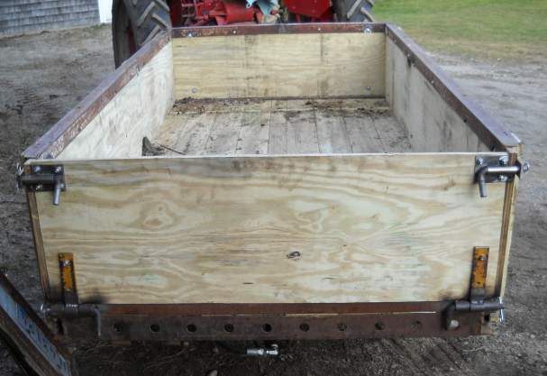
The sideboards are 3/4" pressure treated plywood. I picked up some pre-bent straps intended for making 2x4 gates, welded spacers under them to allow for the offset of the "C" channel, and welded three along each side and two in the front. 2x4 stakes are bolted to the plywood with galvanized carriage bolts and anti-spin washers.
The top rail is off the old trailer that I scrapped. It protects the edges of the plywood and reinforces the sides a little.
As shown, the tailgate is set up for three way operation: Remove the top hinge pins and it hinges down like a pickup truck tailgate. Leave the top pins in and remove the bottom pins and it hinges up like a dump truck tailgate. Remove all four pins to remove the tailgate completely. Final (hopefully) cash outlay was for a sheet of PT plywood, more carriage bolts and the 2x4 straps.
Total cash invested in this project just a hair under $475.